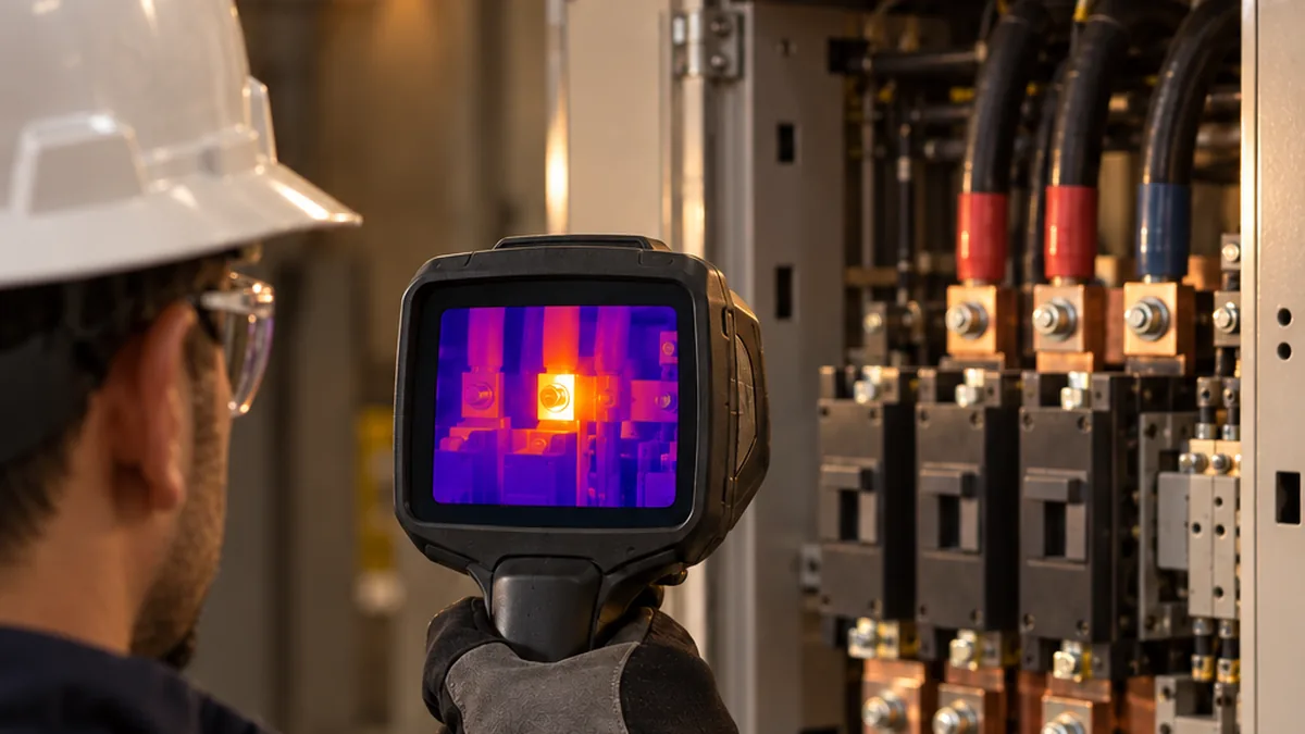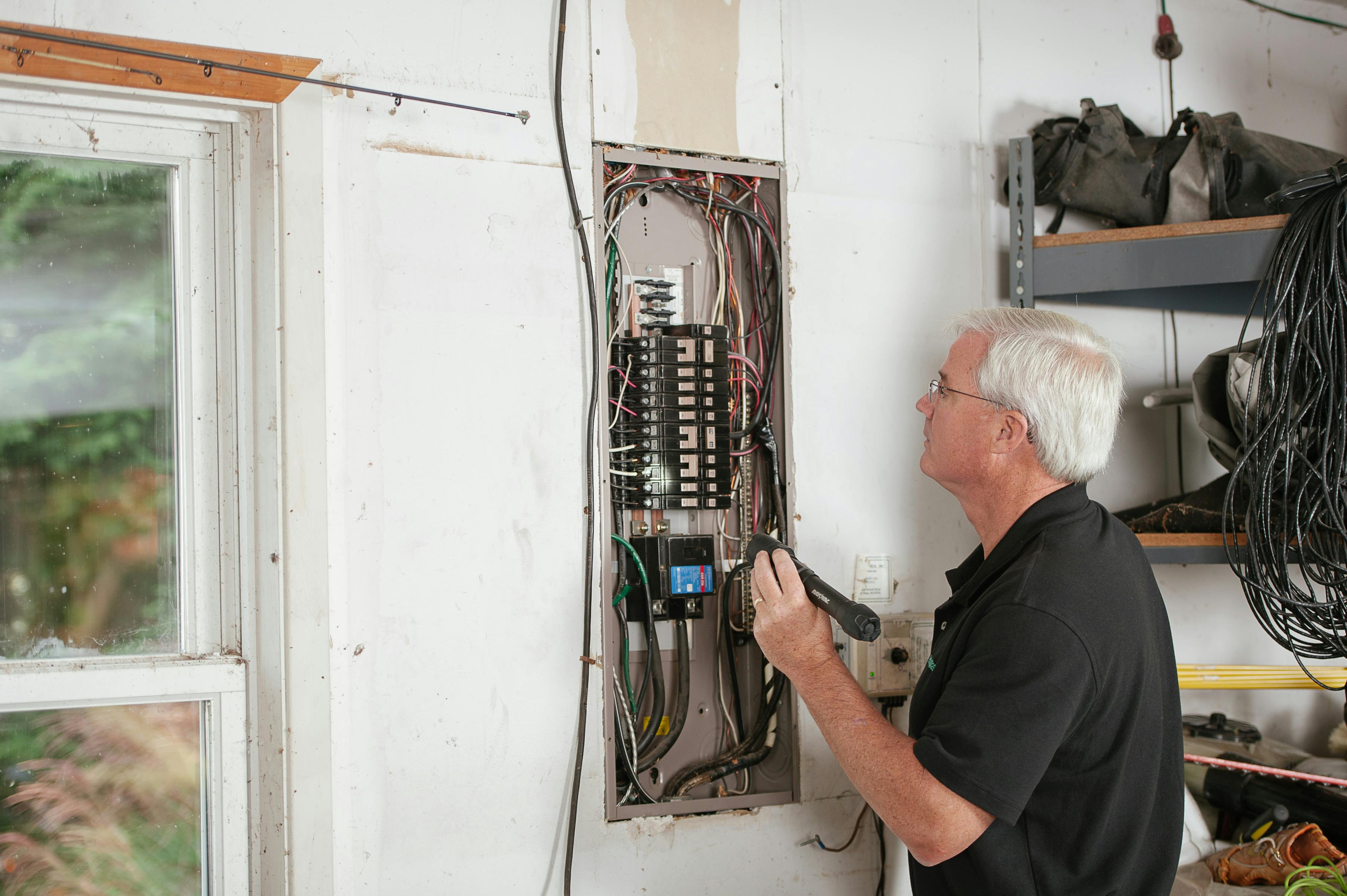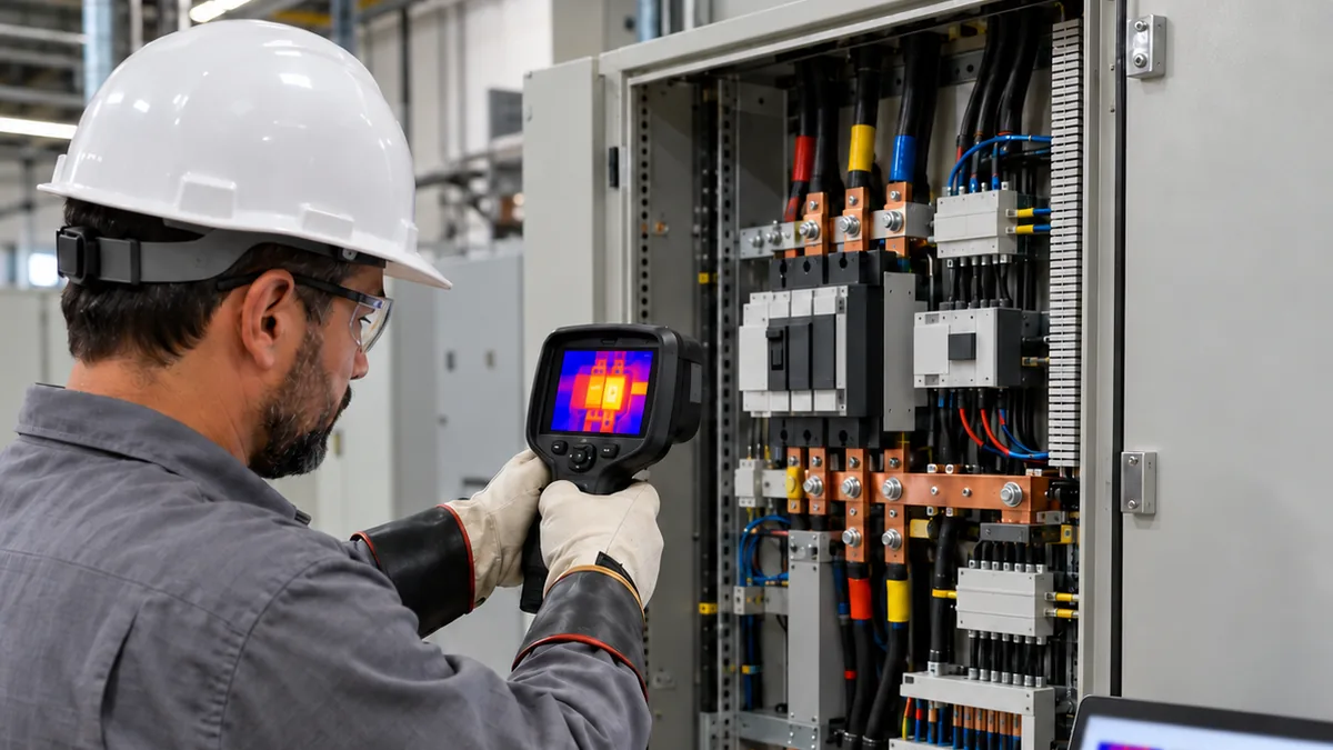
The route ends in the field; reporting continues at the desk
How long does it take you to turn a thermographic inspection route into a technical report? Once the last image is saved, there are still files to export, temperatures to copy, tables to assemble, photographs to arrange and pages to format. Every finding then needs a technical review. Fieldwork is complete, but the deliverable is still unfinished.
That handover matters because the report must retain the context of the measurement. A thermal image without an asset identifier, load condition or comparison reference can be difficult to use for maintenance decisions. Readers need to locate the component, understand the observation and determine what investigation or action should follow.
The process starts before image capture. When the route, images, measurement settings and assessment criteria follow a consistent structure, office work can focus on interpreting records rather than reconstructing missing connections.
Planning the inspection route
Identification, sequence and operating conditions
Prepare a list of equipment and inspection points. Give each point a unique, stable identity: equipment tag, facility, location, panel, circuit and component position, as applicable. Familiar local names can help the team, but they should accompany an identifier that someone outside the inspection crew can recognize.
Arrange the route around access and plant operation. Confirm which assets will be running and the expected load condition. A survey during low demand may not represent the operating condition you need to assess. Agree how to distinguish measured load, information supplied by operations and unavailable data.
Plan the comparison reference as well. It may be a similar component operating under similar load or another reference specified by the procedure. Making that decision in advance prevents the discovery, back at the desk, that the necessary reference image was never captured.
Safety and technical responsibility
A qualified thermographer should perform the inspection. Access to energized panels, opening doors and removing covers require the installation's authorized procedures, risk assessment and appropriate personal protective equipment. Taking a measurement from a distance does not remove electrical hazards.
ABNT NBR 15572:2013 is a Brazilian standard providing guidance on thermographic inspection of electrical and mechanical equipment, including reporting the results. Planning must address access, responsibilities and limitations. If a point cannot be observed safely, document the restriction and arrange inspection under suitable conditions. Follow the standard and safety requirements adopted in the contract and in the country where the work takes place.
What a sound thermographic report should contain
Identification and evidence for each point
Readers should be able to trace every finding to the correct asset without relying on the inspector's memory. A consistent record includes:
- Equipment and location: describe the asset, tag, area, panel, circuit and position of the inspection point. State which areas were actually inspected so the scope of the assessment is clear.
- Thermal image and corresponding visual image: associate both images with the same point and a recognizable view. The visual image locates the component; the thermogram shows the thermal pattern being assessed. Retain the original radiometric file when available.
- Date and time: record when the images were acquired, keeping the inspection date distinct from the report issue date. This allows the finding to be related to the operating conditions at the time.
- Camera and thermographer: include camera model, serial number and calibration record identification, with its date and status as required by the applicable procedure. Identify the responsible thermographer and qualifications relevant to the work.
Measurement settings and operational context
A reported temperature comes from a measurement made under particular conditions. Record the settings actually used and any known limitations:
- Adopted emissivity: state the setting and the basis for selecting it. Low emissivity surfaces require careful consideration of reflections; a material name alone is insufficient justification for a setting.
- Reflected apparent temperature: document the value used and how it was determined. It represents the influence of reflected radiation and should not automatically be treated as equivalent to ambient air temperature.
- Camera-to-object distance: record the distance used for the analysis. Check focus, target size in the image and any obstruction that may limit the component measurement.
- Load condition: describe operation at the time of measurement. Include current and percentage load when available, identifying the basis for the percentage and the source of the information. Distinguish measurements from estimates and values reported by operations.
- Environmental conditions: record ambient temperature and humidity, together with wind and solar exposure outdoors. Explain whether these conditions limit the comparison or require another observation.
Assessment and follow-up
Maintenance teams need evidence accompanied by an interpretation they can review:
- Temperatures and ΔT: report the temperature of the anomalous point, the reference temperature and the difference between them. Identify the reference and explain why it provides a meaningful comparison.
- Severity criteria: state the adopted standard or contractual criterion, its edition and the comparison basis. A classification without an explicit criterion is difficult to review and may imply more certainty than the data supports.
- Probable cause: connect the hypothesis to the observed pattern and load condition. A hot connection may warrant investigating contact resistance, but an image alone does not establish that a connection is loose or oxidized.
- Recommendation and priority: describe the proposed action, any further checks needed and the justification for its priority. Intervention planning must account for the installation's assessment and safety procedures.
- Uninspected or inaccessible areas: identify blocked points, unobservable components and equipment that was not in the required operating condition. Missing coverage should never be interpreted as evidence that no anomaly exists.
This checklist is not a verbatim list of requirements from a single standard. ANSI/NETA MTS addresses equipment description, discrepancies, temperature difference, probable cause, inspection coverage and restrictions, load, images and recommended action. The additional records support measurement traceability and should be tailored to the agreed procedure and scope.
Severity criteria: establish the reference before classifying
Thermal comparison and the effect of load
Use the severity criteria specified in the contract. For example, ANSI/NETA MTS includes Table 100.18, Thermographic Survey — Suggested Actions Based on Temperature Rise, which associates suggested actions with ΔT. It distinguishes comparisons between similar components under similar loading from comparisons between a component and ambient air.
Those comparison bases are not interchangeable. The report should identify which one was used and retain the reference details. The guidance also warns that heating depends strongly on load current. Temperature differences collected under different operating conditions therefore require assessment of that influence before comparison.
Consult the adopted edition when applying its ranges and guidance. This article does not reproduce numerical ΔT bands or temperature limits. Asset criticality, measurement reliability, history and the consequences of failure help inform decisions, while the contracted assessment criterion must remain explicit.
Brazilian references for inspection procedures
Alongside ABNT NBR 15572:2013, ABNT NBR 16969 covers general principles of infrared thermography. ABNT NBR 16818 addresses procedures for applications of the method and received an amendment in November 2025. These ABNT NBR documents are Brazilian standards. Check the applicable document and its updates before establishing the working procedure; outside Brazil, follow the standard or criterion adopted in the contract or the relevant country.
Inspection and measurement references serve a different purpose from a table of suggested actions. Identifying the document used at each stage avoids treating a standard's name as a blanket justification for every conclusion.
Where manual reporting creates bottlenecks
When the inspection record is spread across folders, notes and different camera manufacturers' software, reporting begins with reconciliation. Someone must determine which file belongs to each inspection point, export the images and verify whether the measurement settings remain available after export.
Manually copying temperatures and settings introduces opportunities for typing errors and images assigned to the wrong equipment. Tables built by hand need checking whenever a finding is added. Formatting differences between thermographers create more work to maintain a consistent presentation.
Technical review also takes longer when the reviewer has to open several files to verify a single finding. Scattered historical records complicate comparisons between inspections: a temperature change may reflect a different load, view or reference. Keeping the measurement context is as necessary as keeping the image itself.
How ThermalReports supports the workflow
ThermalReports brings inspection routes, image imports from cameras made by different manufacturers and the organization of findings into one workflow. Inspection points can be linked to equipment and the applicable standard, keeping the evidence connected to the asset identification used along the route.
Assisted anomaly classification helps organize the assessment. The person responsible for the inspection must record the technical criteria used for each analysis, check the reference and review the recommendation. Software assistance does not replace the thermographer's judgment or supply information that was missing during acquisition.
The platform generates structured PDF reports based on technical standards such as ANSI/NETA MTS-2019. Reports bring together your company branding, images and a findings table in a consistent visual format. Once the inspection data is organized and reviewed, the report is ready in minutes.
Its practical value lies in reducing repetitive document assembly and formatting, leaving attention for the technical work: checking measurements, explaining limitations and selecting follow-up actions that match the agreed scope and criteria.
Checklist before issuing the report
- Check asset tags, locations and the pairing of thermal and visual images.
- Review emissivity, reflected apparent temperature, distance, environment and load condition.
- Verify temperatures, the reference, ΔT and the adopted severity criteria.
- Distinguish observations, probable causes and confirmed conclusions; review actions and priorities.
- State inspection exclusions and limitations, and include camera and thermographer details.
- Check dates, times and PDF presentation before issue.
From image capture to the technical deliverable
A complete report starts with a well planned route and ends with a review that preserves the meaning of the evidence. Faster preparation is valuable when identification, measurement settings and assessment criteria remain clear to the people who will carry out maintenance.
Explore ThermalReports at thermalreports.com to see how the platform organizes the work between a thermographic inspection route and the finished technical report.