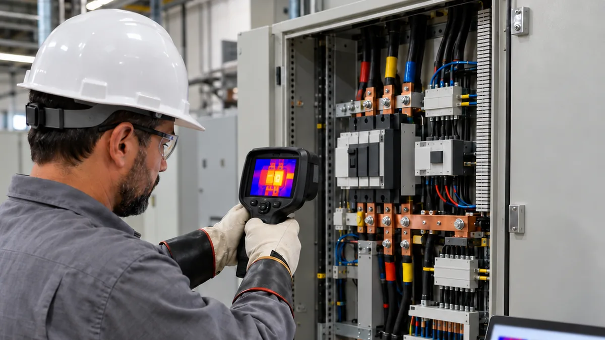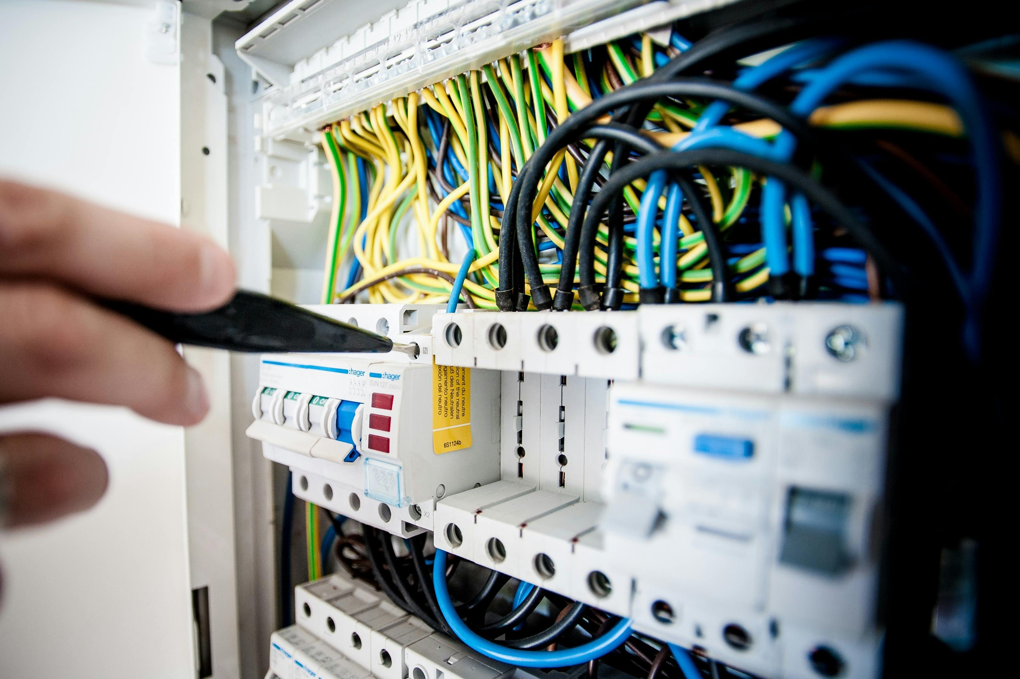
Finding the hot spot is where the diagnosis begins
Thermography of electrical panels makes it possible to observe thermal differences in connections, busbars, circuit breakers and contactors. A hot spot is a sign to investigate: the image alone does not determine the cause of the fault, nor does it authorize an intervention.
This guide covers inspection preparation, load analysis, emissivity, comparison between components and documentation in the report. The goal is to structure the assessment without turning an isolated temperature into an automatic diagnosis.
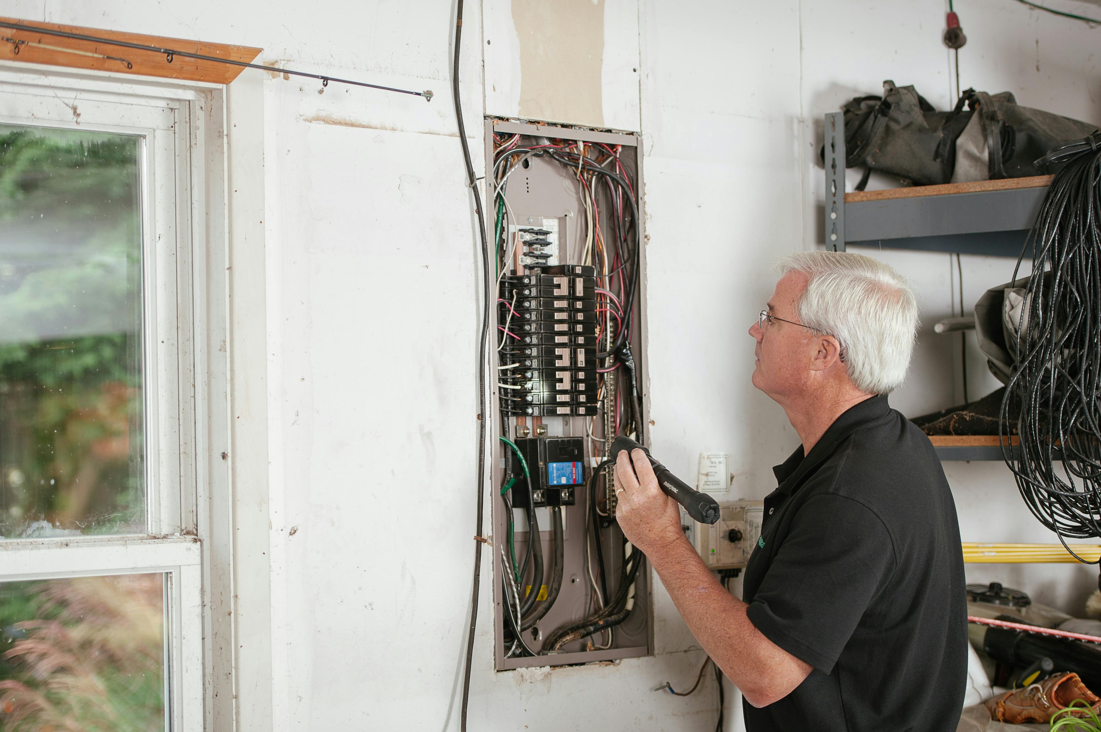
Illustrative image of an electrical panel inspection. Photo: Kathleen Austin Kuhn / Pexels
Preparation and safety before the inspection
Plan the route, identify the panels and confirm with operations which circuits will be in service. Record access limitations before starting data collection. Opening doors, removing guards and working near energized parts depend on the facility's safety procedure.
Brazilian regulatory standard NR-10 (the Brazilian occupational safety standard for electrical installations and services), item 10.2.1 of the text updated in 2019 and made available by the Ministry of Labor and Employment, requires preventive measures based on risk analysis for interventions in electrical installations. See the standard in the Sources section; accessed on October 11, 2026. Do not adopt a generic distance or set of PPE based on this article.
To prepare the record, organize:
- Identification of the panel, circuit, component and phase.
- Operating condition and available load information.
- Instrument, lens and parameters used during data collection.
- Whether equivalent components can be compared.
- Access restrictions and areas that could not be inspected.
Minimum load: document the operating condition
Fluke recommends performing the inspection with the equipment under load and comparing the actual current with the circuit's capacity. The manufacturer's text is linked in the Sources section, accessed on October 11, 2026.
Do not treat a load percentage as a universal requirement. The applicable minimum load must be defined in the inspection procedure, taking into account the equipment and the technical reference adopted. If the observed load does not represent the operation you intend to assess, record that limitation and schedule a new data collection under suitable conditions.
Avoid concluding that a panel is in good condition just because the image was captured during low demand. In the report, distinguish between measured current, information provided by operations and conditions that were not verified.
Emissivity and reflected temperature
Shiny metals can reflect radiation from other sources and make measurement more difficult. FLIR's guidance highlights compensation for emissivity and reflected temperature when assessing low-emissivity surfaces. See the manufacturer's link in Sources; accessed on October 11, 2026.
Record the settings used and how they were determined. Do not copy an emissivity value based only on the material's name, and do not automatically replace reflected temperature with ambient temperature. Also note the distance, focus, viewing angle and any obstacles between the camera and the component.
Do not apply tape or any other material to energized parts to improve the reading without an authorized procedure. When the surface prevents a reliable quantitative assessment, document the restriction and treat the image as an indication for further investigation.
Thermal patterns and fault hypotheses
Loose or oxidized connections
Concentrated heating at a terminal or connection warrants investigation of contact resistance. Compare equivalent connections, check the load and record the location of the heating. Retightening, cleaning or replacement belong to the maintenance stage, carried out according to the procedure and the manufacturer's specifications.
Circuit overload
Distributed heating requires checking the current, the capacity of the components and the operating condition. Do not recommend increasing a circuit breaker's rated current based on the image alone: the electrical analysis must consider the circuit and its protection.
Phase imbalance
A hotter phase calls for comparing the currents and the components. Record whether the compared points have equivalent function and load conditions. The thermal difference helps formulate the hypothesis; complementary measurements help verify it.
Circuit breakers, contactors and relays
Localized heating or a change compared with the history may prompt an investigation of the contacts and of how the component is applied. Compare the finding with previous records and preserve the measurement conditions in the report.
Severity criteria without universal ΔT limits
The temperature difference, or ΔT, expresses the difference between the assessed point and the chosen reference. Identify that reference: an equivalent component and ambient air are different comparisons and must be stated explicitly.
This guide does not establish numerical severity ranges, nor does it attribute repair deadlines to a standard. To prioritize the finding, the responsible engineer or technician must assess the quality of the measurement, the load, the manufacturer's limits, the thermal trend, the criticality of the circuit and the consequences of a failure.
Organize the recommendation in a justifiable way:
- Monitor: document the finding and define the conditions for the next check.
- Investigate: request complementary measurements when the cause or the reliability of the reading is uncertain.
- Plan correction: record the proposed action and the priority approved by the responsible team.
- Communicate risk to operations: escalate signs of an unsafe condition for a decision according to the facility's procedure.
These descriptions are a suggested way to organize the report, not a normative table. The delivery time for a contracted service is the time stated in the proposal; safety decisions and maintenance priorities depend on the assessment of the facility.
Choosing the camera and ensuring data quality
Select a camera and lens suited to the size of the target and the access conditions. Check focus and framing before saving the image. Avoid turning the specifications of a particular camera model into universal minimum requirements.
Preserve the radiometric file, when available, and pair a visual image with the thermal one. If there is no direct access to the component, record what the image actually shows, instead of presenting the temperature of the cover as the temperature of the internal connection.
What to record in the thermographic report
A useful record makes it possible to locate the component and understand how the assessment was carried out. Include:
- TAG, panel, circuit, phase and position of the component.
- Inspection date and identification of the person responsible for data collection.
- Thermal and visual images and the original file, when available.
- Temperature of the point and identification of the reference used for ΔT.
- Load, environmental conditions and recorded measurement parameters.
- Fault hypothesis, limitations of the reading and complementary checks.
- Criterion used for prioritization, recommended action and person responsible for follow-up.
- Proposed conditions for reinspection after the correction.
Separate observation, hypothesis and confirmed diagnosis. This avoids presenting a loose connection, an internal defect or an overload as a conclusion without complementary evidence.
After the inspection
Send the report to operations and maintenance, follow up on how the findings are addressed and plan the reinspection. To compare results, record differences in load and configuration between data collections. The absence of a hot spot under a different operating condition is not, by itself, enough to confirm the fix.
Sources
Sources accessed on October 11, 2026.