Introduction
Circuit breakers are essential protective devices in any electrical system. Responsible for interrupting current flow in the event of overload or short circuit, they protect equipment, installations and people against electrical damage.
When a circuit breaker has faults in its internal contacts, it may fail to operate correctly at the critical moment, leaving the system unprotected. In addition, defective contacts generate excessive heating, which can escalate into catastrophic failures, fires and prolonged outages.
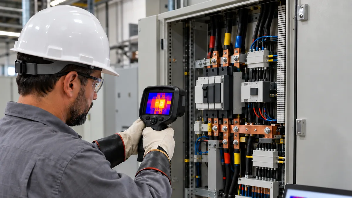
Infrared thermography is a supporting tool for detecting circuit breaker faults before they become serious problems. This technical guide presents the fundamentals of thermographic inspection of circuit breakers, fault patterns, severity criteria and good diagnostic practices.
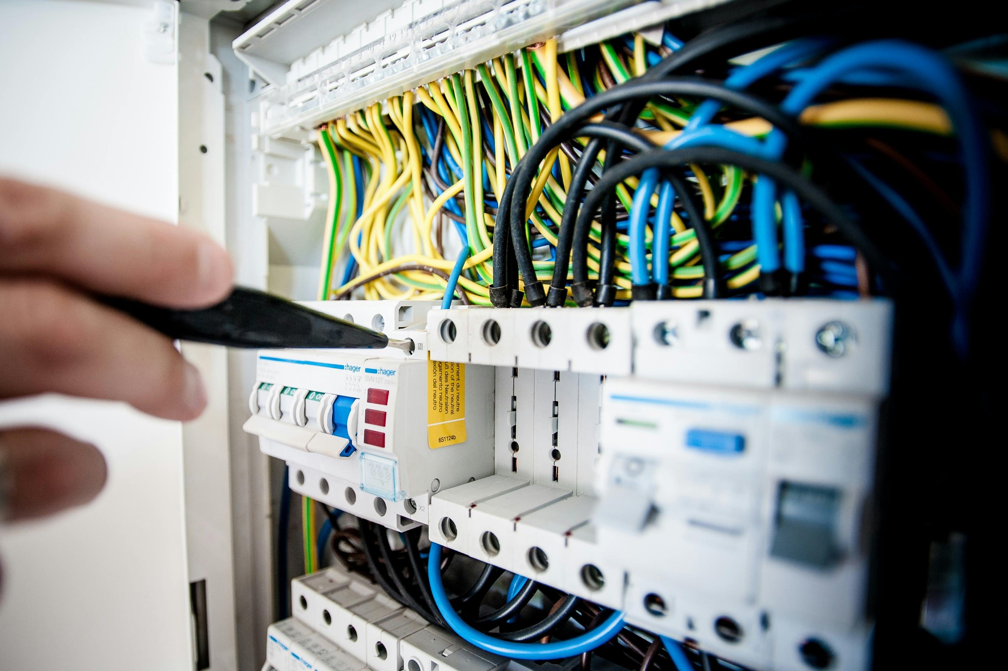
Industrial electrical circuit breakers. Photo: Pixabay / Pexels
Why Use Thermography on Circuit Breakers?
Advantages of Thermographic Inspection
1. Early fault detection — identifies defective contacts before complete failure
2. Non-invasive inspection — the circuit breaker remains energized and in operation
3. Safety — measurement from a distance, without the need to open the equipment
4. Speed — organized data collection in panels with multiple circuit breakers
5. Maintenance prioritization — severity classification guides replacements
6. Historical documentation — tracking of degradation over time
Limitations and Precautions
- Electrical load — the circuit breaker must be carrying representative current
- Visual access — a direct line of sight to the terminals is required
- Emissivity — metal surfaces can reflect radiation from external sources
- Comparison — always compare with similar circuit breakers under the same load
Anatomy of a Circuit Breaker
Main Components
Main contacts:
- Fixed and moving contacts
- Responsible for conducting current
- Subject to wear from electric arcing
Operating mechanism:
- Spring or motor system
- Trip coil
- Manual operating lever
Arc extinguishing chamber:
- Deionizing plates
- Magnetic blowout
- Extinguishing medium (air, SF6, vacuum)
Connection terminals:
- Line side (input)
- Load side (output)
- Clamping screws
Protection relays:
- Thermal (overload)
- Magnetic (short circuit)
- Electronic (adjustable)
Main Causes of Heating in Circuit Breakers
1. Worn Contacts
Mechanism:
- Arc erosion during opening/closing operations
- Reduction of the effective contact area
- Increase in contact resistance
- Localized heating
Thermal symptoms:
- Elevated temperature in the circuit breaker body
- Asymmetric heating between phases
Aggravating factors:
- Excessive number of operations
- Interruption of high currents
- Inadequate maintenance
- Undersized circuit breaker
2. Loose Connections at the Terminals
Mechanism:
- Inadequate torque during installation
- Mechanical vibration
- Differential thermal expansion
- Oxidation of contact surfaces
Thermal symptoms:
- Localized heating at the terminal
- Possible discoloration or signs of arcing
Characteristic pattern:
- Hot spot on the screw or connection bar
- Thermal gradient along the cable
- Normal temperature in the circuit breaker body
3. Continuous Overload
Mechanism:
- Current above the rated capacity
- Joule heating (I²R)
- Accelerated degradation of the contacts
- Premature aging of the insulation
Thermal symptoms:
- Generalized heating of the circuit breaker
- Elevated but evenly distributed temperature
- Moderate but consistent ΔT over time
Indicators to investigate:
- Measured current above the rated capacity
- Progressive heating over several hours
4. Oxidation or Corrosion
Mechanism:
- Formation of an insulating layer on contact surfaces
- Increase in contact resistance
- Localized heating
- Accelerated oxidation (vicious cycle)
Conducive environments:
- High humidity
- Saline atmosphere (coastal regions)
- Industrial pollution (corrosive gases)
- Lack of preventive maintenance
Thermal symptoms:
- Progressive heating over months
- Increasing ΔT between successive inspections
- Elevated temperature even under moderate load

Maintenance on electrical equipment. Photo: Rene Terp / Pexels
Thermal Patterns and Diagnosis
Pattern 1: Localized Heating at the Terminal
Thermal image:
- Hot spot on the screw or connection bar
- Normal temperature in the circuit breaker body
- Thermal gradient along the cable
Hypotheses to confirm:
- Loose or oxidized connection
- Inadequate torque
Assessment:
The priority of the finding must take into account load, manufacturer limits, measurement quality, thermal history and equipment criticality. Document the reference used for comparison and the technical justification for the proposed action. This article does not establish universal temperature ranges or repair deadlines.
Possible actions after technical confirmation:
- De-energize the circuit
- Retighten the connection to the specified torque
- Clean oxidized surfaces
- Apply conductive compound if necessary
Pattern 2: Asymmetric Heating Between Phases
Thermal image:
- One phase significantly hotter than the others
- Heating in the circuit breaker body
Hypotheses to confirm:
- Worn internal contacts on one phase
- Load imbalance
- Supply-side problem
Investigation:
1. Measure the current in each phase
2. Check whether the imbalance is in the circuit breaker or in the supply
3. Compare with adjacent circuit breakers
Possible actions after technical confirmation:
- If load imbalance: redistribute loads
- If worn contacts: replace the circuit breaker
- If supply-side problem: correct it at the source
Pattern 3: Generalized Heating
Thermal image:
- Elevated temperature across the entire circuit breaker
- Uniform heating
- No localized hot spots
Hypotheses to confirm:
- Overload (current above the rated capacity)
- Undersized circuit breaker
- High ambient temperature
Assessment:
The priority of the finding must take into account load, manufacturer limits, measurement quality, thermal history and equipment criticality. Document the reference used for comparison and the technical justification for the proposed action. This article does not establish universal temperature ranges or repair deadlines.
Possible actions after technical confirmation:
- Measure the current and compare it with the nameplate
- Reduce the load if possible
- Assess circuit sizing and protection coordination before proposing changes
- Improve panel ventilation
Pattern 4: Progressive Heating
Thermal history:
- Temperature increasing over months
- ΔT increasing between successive inspections
- Clear degradation trend
Hypotheses to confirm:
- Progressive contact wear
- Accelerated oxidation
- End of the circuit breaker's service life
Possible actions after technical confirmation:
- Schedule preventive replacement
- Increase inspection frequency
- Consider upgrading the protection system
Severity Criteria
The priority of the finding must take into account load, manufacturer limits, measurement quality, thermal history and equipment criticality. Document the reference used for comparison and the technical justification for the proposed action. This article does not establish universal temperature ranges or repair deadlines.
Inspection Best Practices
Preparation
1. Check the load — the circuit breaker must be carrying current under representative load
3. Record conditions — ambient temperature, current, operating time
4. Review the history — check previous inspections and trends
5. Identify critical circuit breakers — prioritize the most important equipment
During the Inspection
1. Keep a safe distance — follow the risk analysis and the facility's procedure
3. Capture multiple angles — terminals, body, connections
4. Measure current — use a clamp meter on each phase
5. Compare with similar units — adjacent circuit breakers under the same load
6. Document the TAG — identification of each circuit breaker
Critical Points to Inspect
1. Line and load terminals
- Connection screws
- Bars or cables
- Contact surfaces
2. Circuit breaker body
- Overall temperature
- Symmetry between phases
- Comparison with similar units
3. Operating mechanism
- Trip coil
- Spring system
- Operating lever
4. Protection relays
- Thermal relay
- Magnetic relay
- Electronic unit
After the Inspection
1. Calculate ΔT — determine severity
2. Generate the report — include images, measurements and recommendations
3. Prioritize actions — follow the severity criteria
4. Inform operations — report critical anomalies immediately
5. Update the history — record thermal trends
6. Schedule maintenance — plan interventions according to priority
Conclusion
Thermography of circuit breakers is an essential tool for predictive maintenance, making it possible to identify contact faults, loose connections and overloads before they escalate into supply interruptions or fires. By following the best practices and severity criteria presented, it is possible to:
- Prevent fires caused by electrical faults
- Extend the service life of circuit breakers
- Optimize maintenance costs
- Improve the reliability of the electrical system
Define the inspection frequency in the facility's maintenance plan, according to criticality, history and operating conditions.
Assessment Criteria and Safety
The priority of the finding must take into account load, manufacturer limits, measurement quality, thermal history and equipment criticality. Document the reference used for comparison and the technical justification for the proposed action. This article does not establish universal temperature ranges or repair deadlines.
Brazilian regulatory standard NR-10 (the Brazilian occupational safety standard for electrical installations and services), in its text updated in 2019, item 10.2.1, requires preventive measures based on risk analysis for electrical interventions. Accessed on October 11, 2026.
Sources
Accessed on October 11, 2026.