Introduction
Electrical substations are critical points in the power distribution system. They concentrate high-voltage equipment such as transformers, busbars, circuit breakers, disconnect switches and insulators — components whose failure can cause prolonged outages, significant material damage and safety risks.
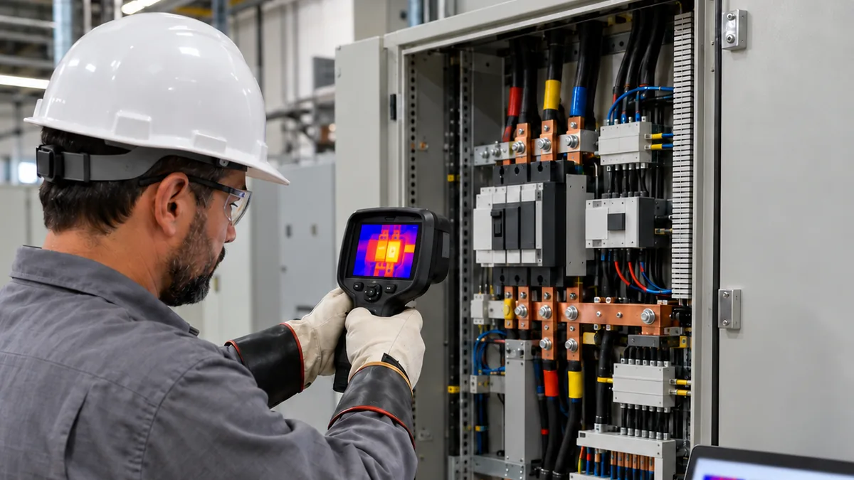
Infrared thermography is an essential tool for predictive maintenance in substations, making it possible to identify hot spots, defective connections and damaged insulators before they escalate into catastrophic failures.
This technical guide presents the fundamentals of thermographic inspection in substations, critical equipment, fault patterns and severity criteria that take the measurement conditions into account.
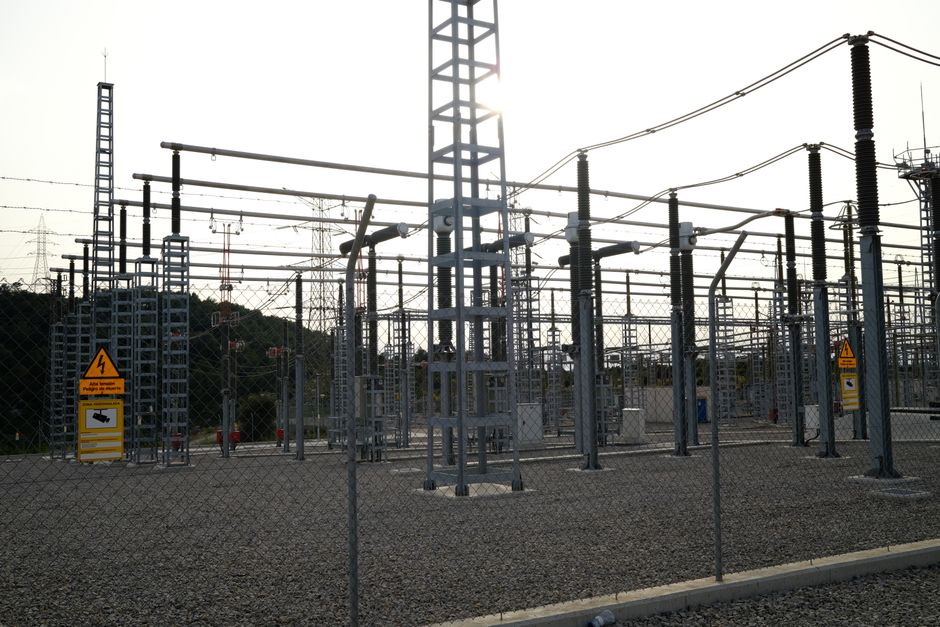
High-voltage electrical substation. Photo: Enric Cruz López / Pexels
Why Use Thermography in Substations?
Advantages of Thermographic Inspection
1. Remote inspection — safety in high-voltage environments
2. Early detection — identifies problems before failure
3. No interruption — equipment remains energized
4. Broad coverage — an inspection route covering accessible equipment
5. Visual documentation — thermal history for trend analysis
6. Maintenance prioritization — severity classification guides interventions
Limitations and Precautions
- Safety distance — respect the controlled zone and the risk zone
- Weather conditions — wind, rain and fog affect measurements
- Electrical load — equipment must be under representative load
- Emissivity — metal surfaces reflect radiation from external sources
- Visual access — a direct line of sight to critical components is required
Critical Equipment in Substations
1. Power Transformers
Inspection points:
- High- and low-voltage bushings
- Input and output connections
- On-load tap changer (OLTC)
- Radiators and cooling system
- Tank and conservator
Common anomalies:
- Heating in bushings (defective internal connection)
- Hot spots on radiators (compromised oil circulation)
- Heating in the tap changer (worn contacts)
- Elevated tank temperature (overload or cooling failure)
Assessment:
The priority of the finding must take into account load, manufacturer limits, measurement quality, thermal history and equipment criticality. Document the reference used for comparison and the technical justification for the proposed action. This article does not establish universal temperature ranges or repair deadlines.
2. Busbars
Inspection points:
- Connections between sections
- Expansion joints
- Connections to equipment
- Supports and insulators
Common anomalies:
- Loose or oxidized connections
- Corrosion at joints
- Circuit overload
- Phase imbalance
Assessment:
The priority of the finding must take into account load, manufacturer limits, measurement quality, thermal history and equipment criticality. Document the reference used for comparison and the technical justification for the proposed action. This article does not establish universal temperature ranges or repair deadlines.

Busbars and insulators in a substation. Photo: Diana ✨ / Pexels
3. Insulators
Types:
- Porcelain insulators
- Polymer insulators
- Through bushings
Inspection points:
- Insulator surface
- Metal connections
- Hardware fittings
Common anomalies:
- Electrical tracking
- Surface contamination
- Cracks or mechanical damage
- Heating in hardware fittings
Characteristic thermal pattern:
- Normal insulator: ambient temperature
- Tracking: localized heating along a line or at a point
- Contamination: diffuse surface heating
4. Circuit Breakers and Disconnect Switches
Inspection points:
- Main contacts
- Input and output connections
- Operating mechanism
- Arc extinguishing chamber
Common anomalies:
- Worn or oxidized contacts
- Loose connections
- High contact resistance
- Inadequate lubrication of the mechanism
Criteria:
5. Surge Arresters
Inspection points:
- Surge arrester body
- Ground connections
- Discharge counter
Common anomalies:
- Internal heating (degraded varistors)
- Internal moisture
- Inadequate ground connection
Thermal pattern:
- Normal: ambient temperature
- Defect: localized or generalized heating
Fault Patterns and Diagnosis
Pattern 1: Loose Connection on a Busbar
Symptoms:
- Localized heating at a joint or connector
- Possible visible discoloration or oxidation
Causes:
- Inadequate torque during installation
- Mechanical vibration
- Electrochemical corrosion
- Differential thermal expansion
Possible actions after technical confirmation:
- Schedule a shutdown
- Clean contact surfaces
- Retighten to the specified torque
- Apply conductive compound if necessary
Pattern 2: Heated Transformer Bushing
Symptoms:
- Elevated temperature at the bushing
- Progressive heating over time
Causes:
- Defective internal connection
- Contamination of the insulating oil
- Insulation degradation
- Transformer overload
Possible actions after technical confirmation:
- Physicochemical analysis of the oil
- Bushing power factor test
- Consider replacement if a defect is confirmed
- Reduce load if overload is identified
Pattern 3: Tracking on an Insulator
Symptoms:
- Localized heating along a line or at a point
- Possible visible carbon marks
Causes:
- Surface contamination (pollution, salt)
- Moisture
- Mechanical damage (crack)
- Material aging
Possible actions after technical confirmation:
- Clean the insulator
- Detailed visual inspection
- Replace if structural damage is confirmed
- Increase the frequency of preventive cleaning
Pattern 4: Heating in a Circuit Breaker
Symptoms:
- Elevated temperature at the contacts
- Asymmetric heating
Causes:
- Worn contacts
- Oxidation
- Mechanical misalignment
- Inadequate contact pressure
Possible actions after technical confirmation:
- Contact resistance test
- Mechanical inspection
- Maintenance or replacement of contacts
- Contact pressure adjustment
Inspection Best Practices
Planning
1. Access authorization — permission to enter the substation
2. Risk analysis — identify hazards and control measures
3. Weather conditions — avoid rain, fog or strong wind
4. Appropriate timing — a period of representative load
5. Calibrated equipment — thermal camera and PPE
Safety
Plan access and risk controls according to the facility's procedure. Do not apply generic distances or PPE to a specific installation.
During the Inspection
1. Systematic scanning — follow a predefined route
2. Multiple angles — capture different perspectives
4. Record ambient temperature — for ΔT calculation
5. Document the TAG — identification of each piece of equipment
6. Note the load — current or power at the time of inspection
After the Inspection
1. Image analysis — identify thermal anomalies
2. Calculate ΔT — determine severity
3. Generate the report — include images, measurements and recommendations
4. Prioritize actions — follow the severity criteria
5. Inform operations — report critical anomalies immediately
Conclusion
Thermography in substations is an essential tool for predictive maintenance, making it possible to identify faults in transformers, busbars, insulators and other equipment before they escalate into supply interruptions. By following the safety best practices and severity criteria presented, it is possible to:
- Reduce unplanned outages
- Increase the reliability of the electrical system
- Prevent damage to high-value equipment
- Improve operational safety
- Optimize maintenance costs
Define the inspection frequency in the facility's maintenance plan, according to criticality, history and operating conditions.
Assessment Criteria and Safety
The priority of the finding must take into account load, manufacturer limits, measurement quality, thermal history and equipment criticality. Document the reference used for comparison and the technical justification for the proposed action. This article does not establish universal temperature ranges or repair deadlines.
Brazilian regulatory standard NR-10 (the Brazilian occupational safety standard for electrical installations and services), in its text updated in 2019, item 10.2.1, requires preventive measures based on risk analysis for electrical interventions. Accessed on October 11, 2026.
Sources
Accessed on October 11, 2026.