What ΔT means in thermography
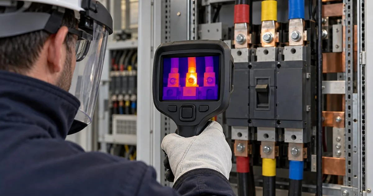
ΔT (delta T) is the temperature difference between the spot that stands out in the thermogram and a reference. When inspecting panels, breakers, busbars, and connections, it usually matters more than absolute temperature, because it shows how much that component is heating beyond what would be expected.
A connection that looks hot may be perfectly normal if the other phases of the same circuit, under the same load, sit at the same level. And a connection that looks only warm can be the most worrying one in the panel if it runs well above its neighboring phases.
The two possible references
ΔT only means something when the report states what it was measured against. There are two common references:
- A similar component under similar load: the other phase of the same breaker, the equivalent terminal on the adjacent circuit, the twin connection on the same busbar. This is the most reliable comparison, because it cancels much of the effect of ambient conditions, emissivity, and reflections.
- Ambient air temperature: used when there is no equivalent component to compare against. It is less sensitive, so the limits used with this reference are wider.
Mixing the two is one of the most common report errors. The same ΔT value can call for immediate repair against a sister phase and only monitoring against ambient air.
Where severity criteria come from
The severity criterion should not be invented by the thermographer or chosen after seeing the result. It has to come from a recognized reference and be stated in the report.
The most widely cited reference for electrical equipment is Table 100.18 of ANSI/NETA MTS (Standard for Maintenance Testing Specifications for Electrical Power Distribution Equipment and Systems), which suggests actions based on temperature rise:
- Possible deficiency; warrants investigation: ΔT between similar components under similar loading: 1 °C to 3 °C; ΔT over ambient air temperature: 1 °C to 10 °C.
- Indicates probable deficiency; repair as time permits: ΔT between similar components under similar loading: 4 °C to 15 °C; ΔT over ambient air temperature: 11 °C to 20 °C.
- Monitor until corrective measures can be accomplished: ΔT between similar components under similar loading: (no equivalent range); ΔT over ambient air temperature: 21 °C to 40 °C.
- Major discrepancy; repair immediately: ΔT between similar components under similar loading: Over 15 °C; ΔT over ambient air temperature: Over 40 °C.
NETA adds important caveats next to the table: temperature specifications vary by type of equipment, heating is generally related to the square of the current (so load has a major impact on ΔT), and the values provide reasonable guidelines in the absence of consensus criteria for the specific apparatus.
In Brazil, ABNT NBR 15572 is the guide for thermographic inspection of electrical and mechanical equipment and defines the responsibilities of the end user and the thermographer. The classification criterion to apply should be the one adopted in the contract or in the company's maintenance program, and the report must say which one it was.
Why load changes everything
Because resistive heating grows with the square of the current, the same defect shows a much smaller ΔT on a lightly loaded circuit. NETA recommends performing surveys during periods of maximum possible loading and identifying load conditions at the time of inspection in the report.
In practice, a small ΔT recorded on an almost idle circuit is not proof of a healthy component. Without the load recorded, the reader of the report has no way to tell.
What the report needs for ΔT to be useful
Among the items NETA lists for a thermographic survey report are the temperature difference between the area of concern and the reference area, the probable cause, the load conditions, thermograms or photographs of the deficient area, and the recommended action. For each anomaly, record:
- Asset and component identification (TAG, panel, circuit, phase)
- Spot temperature and reference temperature, with the type of reference used
- Calculated ΔT
- Load condition at the time of reading
- Emissivity and reflected apparent temperature used
- Thermogram with a visual image
- Severity criterion applied and the resulting classification
- Clear recommendation and timing
How ThermalReports organizes this
ThermalReports was designed so that each anomaly in the report carries its ΔT together with the reference, the load condition, and the stated severity criterion. That way, whoever reviews the document can reproduce the classification without relying on explanations from the person who did the inspection.
To go deeper into reviewing the final document, see also our article on [5 errors that weaken a thermography report](/en/blog/erros-relatorio-termografia-como-evitar).
References: ANSI/NETA MTS, Table 100.18 and notes; ABNT NBR 15572 (scope). The table values are guidelines and do not replace the criterion defined in the maintenance program or the judgment of a qualified professional.